
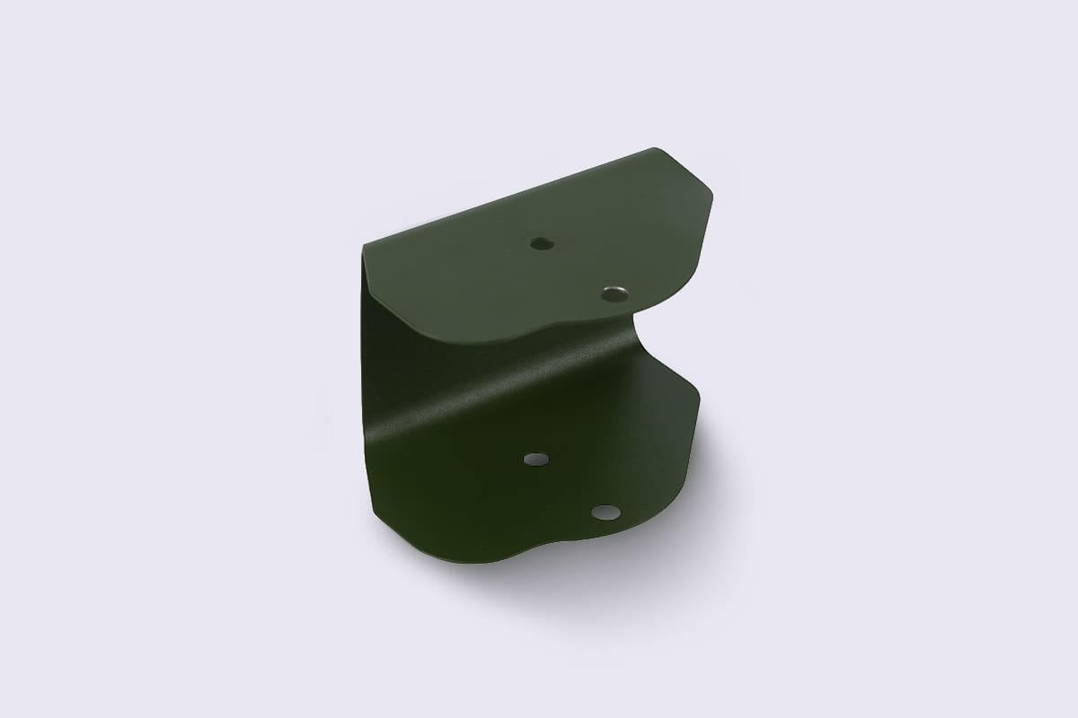
An enclosure may pass inspection as a flat laser-cut blank and still fail when its mounting holes meet the mating chassis. Bending changes the relationship between surfaces, while welding and coating can change it again. The final assembly, not the flat pattern alone, establishes whether the design works. Sheet metal design for manufacturability therefore begins with assembled geometry and follows its effects backward through cutting, forming, joining, and finishing.
Start With the Assembly Interfaces

Before a blank is programmed, the part should have an unambiguous installed position. Hole patterns, flange faces, cable openings, and fastener access must be evaluated against neighboring components. A bracket that looks simple on its own may become difficult to assemble when a return flange obstructs a tool or places a nut beyond reach.
Tolerance allocation also starts at the finished assembly. A mounting hole may need positional control relative to a formed face rather than to an arbitrary edge of the blank. For projects using custom sheet metal fabrication services, a released assembly model and clearly identified locating features give the fabricator a better basis for choosing bend sequence, tooling, and inspection datums.
The corresponding flat-pattern DXF is useful, but it cannot replace these functional references. Flat-state hole coordinates and finished-state hole positions answer different questions. A drawing that lacks a clear bent-state datum scheme may allow two plausible inspection methods, a particular concern for enclosures assembled from several folded panels.
Translate Bend Geometry Into a Real Flat Pattern
A bend is a zone of tensile and compressive strain, not a zero-width line. Its developed length depends on material thickness, inside radius, and the position of the neutral axis. The K-factor approximates that neutral-axis location for flat-pattern calculations; a value suited to one material and die combination may not transfer cleanly to another.
A starting inside bend radius near one material thickness is often useful, but harder alloys and specific grain directions may require a different choice. Bending too tightly can produce surface cracking or dimensional variation. Press-brake forming and bend-radius assessment are among the fabrication tasks performed by Hanstar Technologies, which works with 5052 and 6061 aluminum, stainless steels 304 and 316, and cold-rolled or galvanized steels.
Material grade and gauge must be fixed before bend deductions are treated as final. A test bend can establish a practical deduction for the selected tooling, which is safer than assuming a software default applies to every press-brake setup.
Prevent Hole Distortion and Corner Damage
Features too close to the bend zone may stretch or lose their intended shape during forming. A general design check flags holes within roughly twice the sheet thickness of a bend edge, although the actual risk changes with bend radius, tooling, and hole size. Critical holes can sometimes be repositioned, pierced later, or given an appropriate manufacturing allowance.
Corner reliefs deserve equal attention. Without enough clearance, intersecting bends can bunch material, tear a flange, or interfere with the intended sequence of operations. Relief geometry should avoid sharp, fragile remnants while retaining the strength needed around fasteners.
During a review of custom sheet metal fabrication services, hole-to-bend distances and relief placement should be assessed together; solving one feature in isolation can create another conflict at the adjacent flange.
Treat Welding, Finishing, and Hardware as Design Inputs
A welded frame acquires heat and restraint as joints are made, so its distortion pattern depends on joint location and sequence. Positioning features and inspection checks should reflect the assembled condition. Hardware such as threaded inserts or studs must also have adequate edge clearance, bearing area, and access for installation equipment.
Coating thickness, electrical contact surfaces, and cosmetic requirements can further affect the outcome. A powder-coated joint may need a masked surface, while anodized aluminum and plated steel impose different material and process constraints. Hanstar Technologies provides laser cutting, CNC bending, TIG, MIG, and spot welding, as well as finishing and hardware installation.
Its formed-part dimensional tolerance is typically around ±0.1 mm, subject to the geometry and material; critical fit requirements need separate review. Several bends and joints can produce cumulative position error even when individual operations remain within their nominal limits. Fixture points, joint order, and the stage at which threaded hardware is installed should therefore be included in the final-fit discussion.
The most useful inspection plan checks the surfaces and dimensions on which assembly actually depends, not only the dimensions easiest to measure on a flat part. A project involving custom sheet metal fabrication services can include a fit-up sample before repeat batches, particularly when multiple formed and welded components must align. The same release package should identify surface treatment, visible faces, joint requirements, and any inserts required before shipment.
Good sheet metal DFM makes the final assembled condition the reference point for every earlier operation. Hanstar Technologies handles prototypes through production batches with coordinated forming, joining, and finishing. Where post-weld hole alignment governs acceptance, a fit-up review can be requested using the assembled-state drawing and flat pattern.
